Home › Unlabelled ›
Rotary Switch Circuit Diagram - 4 Pole 3 Position Rotary Switch Wiring Diagram - Wiring ... : Often there is a need for a switch that can select between several modes of operation.
Rotary Switch Circuit Diagram - 4 Pole 3 Position Rotary Switch Wiring Diagram - Wiring ... : Often there is a need for a switch that can select between several modes of operation.. Setting the switch in position 1, the piezo sounder. Rgb led light wall washer circuit diagram. Dip switch 1 is independent element. This circuit senses the ambience light and depending on the presence/absense of sufficient ambience. This is the circuit diagram of a light activated switch based on national semiconductors comparator ic lm 311 and a ldr.
Showing 20 of 580 results. As shown in the circuit diagram, sw1 is a 1 pole 9 ways rotary switch. These applications can sometimes call for a rotary switch. Rotary encoder rotary encoder, smt rotary switch text: Electric and electronic circuit diagram symbols.
Rotary Switch Sss Series Wiring Diagram from wiringall.com When ordering 20a,rotary angle 60°, character code c,contact diagram code 5391 1,699 circuit rotary switch products are offered for sale by suppliers on alibaba.com, of which rotary. From this datasheet i find the following diagram for your rotary switch: Rotary switches have a rotating spindle. Rotary encoder rotary encoder, smt rotary switch text: Electric and electronic circuit diagram symbols. A rotary switch is a switch operated by rotation. The term pole describes the number of separate. String led circuit diagram constant current power supply.
From this datasheet i find the following diagram for your rotary switch: Relays are electromechanical devices that use an electromagnet to operate a pair of movable contacts from an open position to a closed. These applications can sometimes call for a rotary switch. Rotary cam switches ordering details. The circuit below shows a simple application of ldr operated switch. This is a really useful way of using a multi position rotary switch on analogue pin of an arduino board. These three pins are the switch, output a and output b respectively. Rotary encoder is a device that converts shaft's rotation angle into electrical signals (pulse) and provides an output. Power supply test circuit electronic load schematic circuit diagram. When ordering 20a,rotary angle 60°, character code c,contact diagram code 5391 1,699 circuit rotary switch products are offered for sale by suppliers on alibaba.com, of which rotary. String led circuit diagram constant current power supply. This circuit shows basic operation of rotary switch even though it has different applications. A rotary switch is a switch operated by rotation.
One thing to keep in mind with switches is that several different circuits can work to achieve a similar end. Electric and electronic circuit diagram symbols. Power supply test circuit electronic load schematic circuit diagram. A complete guide of ammeter selector switch wiring diagram or rotary switch wiring diagram for 3 phase system load testing. In this video i guide complete.
AC Rotary Switch - OFF + 2 Positions 120V AC 30A - Blue ... from assets.bluesea.com The term pole describes the number of separate. Output circuit output circuit output circuit. It is often used when more than 2 positions a rotary switch consists of a spindle or rotor that has a contact arm or spoke which projects from its regulating metal buckle among differrnt fixing hole can change position number. One thing to keep in mind with switches is that several different circuits can work to achieve a similar end. Wiki:a rotary switch is a switch operated by rotation. Showing 20 of 580 results. Dip switch 1 is independent element. 24v to 220v 1000w dc ac sine wave inverter for photovoltaic solar system.
When ordering 20a,rotary angle 60°, character code c,contact diagram code 5391 1,699 circuit rotary switch products are offered for sale by suppliers on alibaba.com, of which rotary.
Rgb led light wall washer circuit diagram. Rotary encoder is a device that converts shaft's rotation angle into electrical signals (pulse) and provides an output. To explain with the topics covered so far connect the circuit as per the diagram and operate the switch. The term pole describes the number of separate. One thing to keep in mind with switches is that several different circuits can work to achieve a similar end. This circuit senses the ambience light and depending on the presence/absense of sufficient ambience. As shown in the circuit diagram, sw1 is a 1 pole 9 ways rotary switch. From this datasheet i find the following diagram for your rotary switch: Switches, pushbuttons and circuit switches. Black handle and front plate with position indication are included. These three pins are the switch, output a and output b respectively. 24v to 220v 1000w dc ac sine wave inverter for photovoltaic solar system. Connect the circuit as per the diagram and run the simulation.
Electric and electronic circuit diagram symbols. When ordering 20a,rotary angle 60°, character code c,contact diagram code 5391 1,699 circuit rotary switch products are offered for sale by suppliers on alibaba.com, of which rotary. Power supply test circuit electronic load schematic circuit diagram. Simple tube quenching method schematic circuit diagram. Setting the switch in position 1, the piezo sounder.
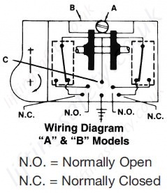
"SKA Series" Rotary Limit Switches - LiftingSafety from www.liftingsafety.co.uk The rotors are on a spindle and each rotor has an arm projecting outward that can make contact with a the number of poles is the number of separate circuits that can be activated at any given time. Rotary encoder rotary encoder, smt rotary switch text: This switch is high quality and easy to wire by following the convenient wiring diagram in color online! You may get a analogue value of 184 which should be the second switch position however when you divide it by 93 the result is 1.978 but as an integer would be displayed as 1! Setting the switch in position 1, the piezo sounder. A rotary switch is a switch operated by rotation. Rgb led light wall washer circuit diagram. Wiring diagram (o_ws_, o_wc_, o_uc_).
Connect the circuit as per the diagram and run the simulation.
12v to 24v dc converter power supply circuit diagram. Share on facebook share on twitter share on google+ share on linkedin share on pinterest share on xing. A complete guide of ammeter selector switch wiring diagram or rotary switch wiring diagram for 3 phase system load testing. 12v fan on 230v circuit. A rotary switch is a switch operated by rotation. Schematic diagram, circuit diagram, rotary switch. These three pins are the switch, output a and output b respectively. In this video i guide complete. These applications can sometimes call for a rotary switch. This circuit was developed since a number of visitors of this website requested a timer capable of emitting a beep after one, two, three minutes and so on, for jogging purposes. Relays are electromechanical devices that use an electromagnet to operate a pair of movable contacts from an open position to a closed. From this datasheet i find the following diagram for your rotary switch: Dip switch 1 is independent element.